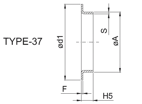
We produce Collars made from plates, with dimensions and tolerances in accordance with EN 1092-1 (Din 2642) or for lap joint flanges according to Asme B16.5.


| Ø NPS | Ø DN |
| 1/2 | 15 |
|
For flanges ANSI 150# Diameter of lap Radius of fillet Height |
|
| 3/4 | 20 |
|
For flanges ANSI 150# Diameter of lap Radius of fillet Height |
|
| 1 | 25 |
|
For flanges ANSI 150# Diameter of lap Radius of fillet Height |
|
| 1 1/4 | 32 |
|
For flanges ANSI 150# Diameter of lap Radius of fillet Height |
|
| 1 1/2 | 40 |
|
For flanges ANSI 150# Diameter of lap Radius of fillet Height |
|
| 2 | 50 |
|
For flanges ANSI 150# Diameter of lap Radius of fillet Height |
|
| 2 1/2 | 65 |
|
For flanges ANSI 150# Diameter of lap Radius of fillet Height |
|
| 3 | 80 |
|
For flanges ANSI 150# Diameter of lap Radius of fillet Height |
|
| 3 1/2 | 90 |
|
For flanges ANSI 150# Diameter of lap Radius of fillet Height |
|
| 4 | 100 |
|
For flanges ANSI 150# Diameter of lap Radius of fillet Height |
|
| 5 | 125 |
|
For flanges ANSI 150# Diameter of lap Radius of fillet Height |
|
| 6 | 150 |
|
For flanges ANSI 150# Diameter of lap Radius of fillet Height |
|
| 8 | 200 |
|
For flanges ANSI 150# Diameter of lap Radius of fillet Height |
|
| 10 | 250 |
|
For flanges ANSI 150# Diameter of lap Radius of fillet Height |
|
| 12 | 300 |
|
For flanges ANSI 150# Diameter of lap Radius of fillet Height |
|
| 14 | 350 |
|
For flanges ANSI 150# Diameter of lap Radius of fillet Height |
|
| 16 | 400 |
|
For flanges ANSI 150# Diameter of lap Radius of fillet Height |
|
| 18 | 450 |
|
For flanges ANSI 150# Diameter of lap Radius of fillet Height |
|
| 20 | 500 |
|
For flanges ANSI 150# Diameter of lap Radius of fillet Height |
|
| 22 | 550 |
|
For flanges ANSI 150# Diameter of lap Radius of fillet Height |
|
| 24 | 600 |
|
For flanges ANSI 150# Diameter of lap Radius of fillet Height |
|
Unless otherwise indicated, dimensions are in mm.
These fittings are not included in the ASME/ANSI 16.9 standard.
These dimensions conform to the radius established for lap joint flanges in ASME B16.5.
The dimensions “R” and “h” are indicatives only.
A minimum wall thickness of 87.5% applies unless the purchaser specifies a different wall thickness tolerance.
Out of round is the sum of absolute values of plus and minus tolerances.
Gasket face finish shall be in accordance with ASME B16.5 for raised face flanges (note 1). The most common finish is the Stock Finish.
| Ø DN | |
| 10 | |
|
A Tolerance on wall thickness PN 2.5 PN 6 PN 10 (DIN 2642) PN 16 A PN 2,5 to PN 10 PN 16 CHAMFER |
|
| 15 | |
|
A Tolerance on wall thickness PN 2.5 PN 6 PN 10 (DIN 2642) PN 16 A PN 2,5 to PN 10 PN 16 CHAMFER |
|
| 20 | |
|
A Tolerance on wall thickness PN 2.5 PN 6 PN 10 (DIN 2642) PN 16 A PN 2,5 to PN 10 PN 16 CHAMFER |
|
| 25 | |
|
A Tolerance on wall thickness PN 2.5 PN 6 PN 10 (DIN 2642) PN 16 A PN 2,5 to PN 10 PN 16 CHAMFER |
|
| 32 | |
|
A Tolerance on wall thickness PN 2.5 PN 6 PN 10 (DIN 2642) PN 16 A PN 2,5 to PN 10 PN 16 CHAMFER |
|
| 40 | |
|
A Tolerance on wall thickness PN 2.5 PN 6 PN 10 (DIN 2642) PN 16 A PN 2,5 to PN 10 PN 16 CHAMFER |
|
| 50 | |
|
A Tolerance on wall thickness PN 2.5 PN 6 PN 10 (DIN 2642) PN 16 A PN 2,5 to PN 10 PN 16 CHAMFER |
|
| 65 | |
|
A Tolerance on wall thickness PN 2.5 PN 6 PN 10 (DIN 2642) PN 16 A PN 2,5 to PN 10 PN 16 CHAMFER |
|
| 80 | |
|
A Tolerance on wall thickness PN 2.5 PN 6 PN 10 (DIN 2642) PN 16 A PN 2,5 to PN 10 PN 16 CHAMFER |
|
| 100 | |
|
A Tolerance on wall thickness PN 2.5 PN 6 PN 10 (DIN 2642) PN 16 A PN 2,5 to PN 10 PN 16 CHAMFER |
|
| 125 | |
|
A Tolerance on wall thickness PN 2.5 PN 6 PN 10 (DIN 2642) PN 16 A PN 2,5 to PN 10 PN 16 CHAMFER |
|
| 150 | |
|
A Tolerance on wall thickness PN 2.5 PN 6 PN 10 (DIN 2642) PN 16 A PN 2,5 to PN 10 PN 16 CHAMFER |
|
| 200 | |
|
A Tolerance on wall thickness PN 2.5 PN 6 PN 10 (DIN 2642) PN 16 A PN 2,5 to PN 10 PN 16 CHAMFER |
|
*+/-1%, max +/-3,0 mm
Unless otherwise indicated, dimensions are in mm.
Dimensions in brackets are valid only for DIN 2642.
These collars are for use with type 02 flanges (loose plate flanges).
On request we can produce collars type 32, 33, 35 and 36.
| Ø NPS | Ø DN | Ø mm |
| 1/2 | 15 | 21,3 |
|
ASME B36.19M ASME B36.10M |
||
| 3/4 | 2032 | 26,7 |
|
ASME B36.19M ASME B36.10M |
||
| 1 | 25 | 33,4 |
|
ASME B36.19M ASME B36.10M |
||
| 1 1/4 | 32 | 42,2 |
|
ASME B36.19M ASME B36.10M |
||
| 1 1/2 | 40 | 48,3 |
|
ASME B36.19M ASME B36.10M |
||
| 2 | 50 | 60,3 |
|
ASME B36.19M ASME B36.10M |
||
| 2 1/2 | 65 | 73 |
|
ASME B36.19M ASME B36.10M |
||
| 3 | 80 | 88,9 |
|
ASME B36.19M ASME B36.10M |
||
| 3 1/2 | 90 | 101,6 |
|
ASME B36.19M ASME B36.10M |
||
| 4 | 100 | 114,3 |
|
ASME B36.19M ASME B36.10M |
||
| 5 | 125 | 141,3 |
|
ASME B36.19M ASME B36.10M |
||
| 6 | 150 | 168,3 |
|
ASME B36.19M ASME B36.10M |
||
| 8 | 200 | 219,1 |
|
ASME B36.19M ASME B36.10M |
||
| 10 | 250 | 273 |
|
ASME B36.19M ASME B36.10M |
||
| 12 | 300 | 323,8 |
|
ASME B36.19M ASME B36.10M |
||
| 14 | 350 | 355,6 |
|
ASME B36.19M ASME B36.10M |
||
| 16 | 400 | 406,4 |
|
ASME B36.19M ASME B36.10M |
||
| 18 | 450 | 457 |
|
ASME B36.19M ASME B36.10M |
||
| 20 | 500 | 508 |
|
ASME B36.19M ASME B36.10M |
||
| 22 | 550 | 559 |
|
ASME B36.19M ASME B36.10M |
||
| 24 | 600 | 610 |
|
ASME B36.19M ASME B36.10M |
||